
SMT fasteners PCB spacing and stacking reference between boards
SMT Tape-and-Reel Packaging
Product photos
Actual photos, not renders
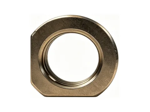
Illustration note
The image shows an actual part of this specification; appearance differs with surface treatment and head style, and the delivered part prevails.
Images are for appearance and structure reference; dimensions and tolerances are subject to the specifications and the applicable standards on this page.
Product description
Compiled from the existing technical description of this product on this site
SMT spacer blocks are made of highly conductive copper alloy or free-cutting steel, with optimized tin plating to ensure full solder joints. External dimensions are precisely controlled; used for stacking, spacing or enclosure assembly between PCBs, they support tape & reel packaging and fully automatic placement, providing an accurate height and position reference for structural assembly.
Specifications
The parameters listed on this page are subject to final inspection and the applicable standards; items not listed follow the customer drawing or the order agreement and are not committed by default.
| Material | Copper alloy / free-cutting steel |
|---|---|
| Surface treatment | Tin plating |
| Standard | Per customer drawing / company standard; solderability per IPC/JEDEC J-STD-002; carrier tape packaging per EIA-481 |
| Typical application | PCB spacing and stacking reference between boards |
Spec lookup
Based on your operating conditions, look up directly among the 8 models in this series — pure front-end filtering, no redirects, no URL changes
Filter results are based on the specification fields published on each model page and are for preliminary screening only; the final selection must be confirmed in light of the actual load, plate thickness and assembly process.
Drawings & customization
No public catalogue is available for this series; drawing-based requests are handled per project.
Made to drawing / sample replication
A 2D drawing or a physical sample is enough for evaluation; once confirmed, we issue drawings, build samples and obtain first-article approval before volume production. Drawings and project information are handled under confidentiality requirements.
Manufacturing process
The usual process route for this product family; actual operations follow the drawing and order requirements.
- Precision turning / cold headingPan head and thread forming
- End-face and thread machiningFlatness control of the mounting surface
- ElectroplatingMatte tin / nickel plating, reflow-compatible
- Tape packagingCompatible with SMT placement equipment
- Full inspection of dimensions and platingPlacement and soldering compatibility verification
Capacity & delivery
Taken from the company's published capacity and certification information; no unverified claims are included.
FAQ
Material, standards, surface treatment and installation points for this model; the data comes from the specification table on this page and from the national standards cited in the answers.
Q1What material is the SMT spacer block made of? What strength level does it achieve?
Materials listed in the specification table on this page: copper alloy / free-cutting steel. Material certificates and mechanical property test reports can be provided with delivery; batch acceptance follows the above specifications.
Q2Which applications is the SMT spacer block suitable for?
Typical applications listed in the product description on this page: multilayer board stacking structures; communication and server boards; consumer electronics assembly; automotive electronics modules. Overview: SMT spacer blocks are made of highly conductive copper alloy or free-cutting steel, with optimized tin plating to ensure full solder joints. External dimensions are precisely controlled; used for stacking, spacing or enclosure assembly between PCBs, they support tape & reel packaging and fully automatic placement,
Q3What are the main features of the SMT spacer block?
Features listed in the product description on this page: precisely controlled external dimensions for accurate stacking height; tin plating for full joints and good solderability; support for tape & reel packaging and fully automatic placement; copper alloy / free-cutting steel options balancing conductivity and strength.
Q4To which standards is the SMT spacer block produced and accepted?
Standards listed in the specification table on this page: per customer drawing / company standard; solderability per IPC/JEDEC J-STD-002; carrier tape packaging per EIA-481. Dimensional inspection reports can be provided with delivery; batch acceptance is carried out according to the above standards and the drawings agreed by both parties.
Q5How is the solderability of the SMT spacer block ensured?
Solderability of the tin plating is evaluated per IPC/JEDEC J-STD-002; solder joint appearance and acceptance refer to IPC-A-610. Batch solderability testing is performed with each order to ensure compatibility with reflow and wave soldering. (Applies to this model, the SMT spacer block.)
Related models
Alternative sizes in the same series and cross-series fasteners commonly used together
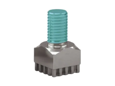
SMT fasteners
PCB Solder Standoffs / Nut Columns
PCB high-current terminal, designed for high-current scenarios and soldered onto the PCB, providing a low-resistance
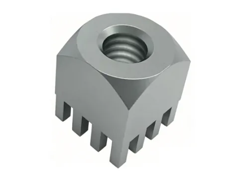
SMT fasteners
PCB High-Current Terminal 1
High-current crimp terminal, made of selected high-conductivity alloy with a precision cold-heading process and a special electroless plating; contact resistance is extremely low, suitable for high-power connections
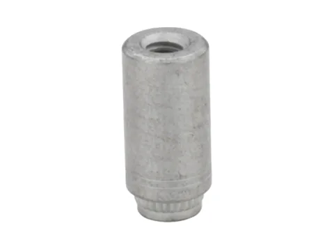
SMT fasteners
1.2mm PCB Internal/External Thread Super Screw
PCB solder standoff, made of free-cutting steel or copper alloy, tin-plated to optimize solderability. A precision locating step at the base
Direct Assembly
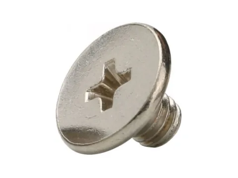
0.6 mm CM Phillips Ultra-Thin Ultra-Short Large-Head Micro Screw
A 0.6 mm ultra-thin large-head design that pushes space utilisation to the limit, effectively increasing the contact area and preventing the sheet from being pierced. Precision Phillips drive combined with a very short thread body.
Insert Screws
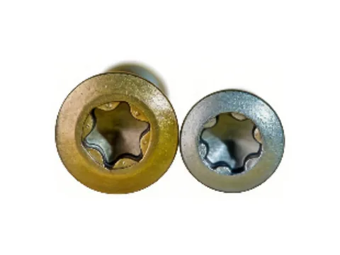
TORX PLUS Insert Screws
Made of class 12.9 high-strength alloy steel