
Micro precision fastener solutions|M0.6–M1.4, micron levelA low head saves spaceTape-fed SMT
M0.6 is not a scaled-down M6. Its pitch is only in the 0.15 mm range, the effective thread length may be barely over 1 mm, and the pitch-diameter tolerance is measured in microns — a slight deviation in thread form and the go/no-go gauge fails, a small defect in the head and it snaps during tightening. The difficulty with micro parts is not making them small, but making every single one the same. The specifications on this page cover M0.6–M1.4 and board-level precision parts.

Five real difficulties with micro screws
The smaller the size, the more the difficulty rises exponentially. Each point below is taken from in-house technical articles and product pages and can be checked one by one.
Effective engagement is barely over 1 mm, leaving almost no margin for error
An M6 bolt often has ten-odd millimetres of effective thread engagement, while an M0.6 micro screw may have barely over 1 mm. That means a single incomplete thread removes a large share of the load capacity; thread height and pitch-diameter tolerance are both at micron level, and a slight deviation fails the gauge. Micro parts cannot be designed by proportional scaling — they have to be recalculated from the number of threads.
A conforming single piece is not enough — the lot must be consistent
Micro screws almost always run on automatic assembly lines: head diameter, shank diameter, length and recess depth must vary only within a very narrow band per lot, otherwise parts jam, the bit slips or the head breaks off. That is why the key metric for micro parts is not how good a single piece can be, but how good every single piece is — consistency translates directly into line yield.
No tape, no production line
Modern lines are fully automated precision assembly, so screws must run in Tape & Reel and keep pace with the SMT cycle. A screw with excellent performance that does not feed reliably through the tape counts as zero on the line. Micro parts therefore have to consider the pick-up surface, tape orientation and reel compatibility from the design stage.
Stainless steel does not harden into strength; choose the material by function
Carbon steel (SWRCH10A/18A/22A) can be carburized to raise surface hardness and wear resistance, and is the standard choice for light-load structural parts. SUS302HQ/304/316 cannot gain strength from heat treatment, but they offer low permeability and corrosion resistance, which suits medical and interference-sensitive locations. Where high strength and stainless properties are both required, only hardenable SUS410 or carburized carbon steel will do; for strict non-magnetic requirements, choose titanium TA2.
The coating must neither clog the thread nor change the fit clearance
On micro parts the coating thickness and the thread tolerance are in the same order of magnitude: a slightly thicker coating and the gauge will not pass, a slightly thinner one and corrosion resistance falls short. Surface treatment for micro parts must therefore be designed together with the thread tolerance (pre-plating dimensions allowed for), and the go/no-go check must be made after plating. On large parts this is absorbed by the tolerance margin; on M0.6 it is not.
All specifications, grouped as M0.6–M1.4 micro parts and board-level precision parts.
Micro parts handle thin walls and narrow spaces; board-level parts handle cross-board fastening between PCB and modules. Each card links straight to its product page, where head style, specifications and surface treatment are authoritative.
M0.6–M1.4 micro screws
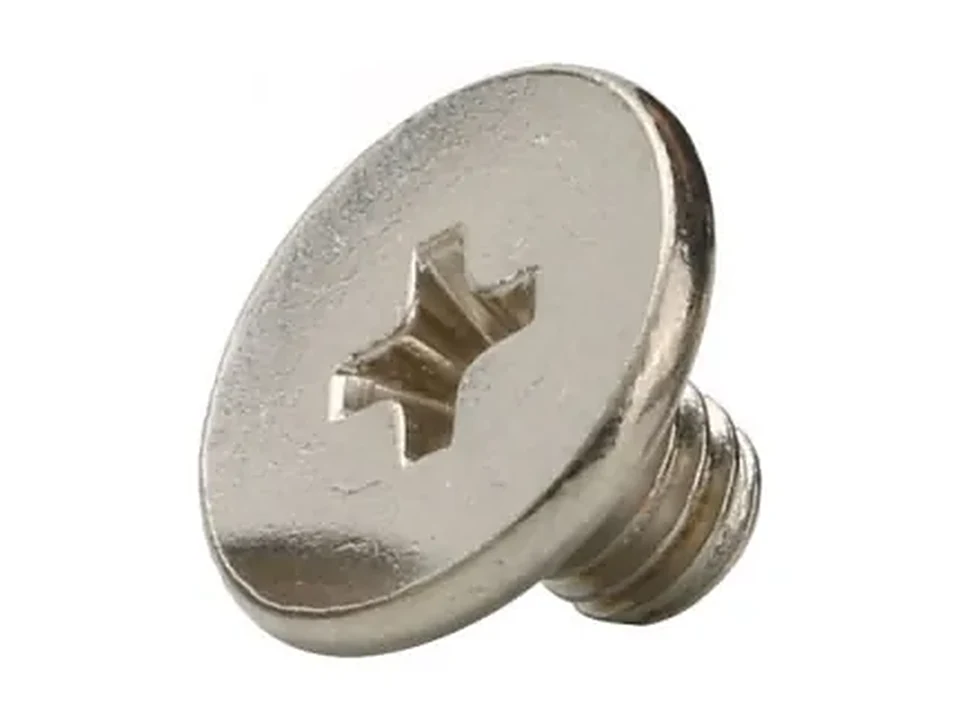
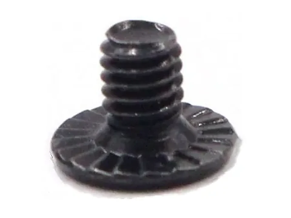
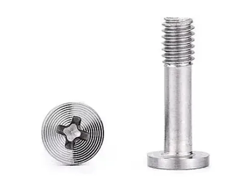
3 SKUsAimed at tight spaces such as phone mid-frames, watch movements, camera modules, AI hardware and robot joints. Ultra-low heads save height, and serrated or CD-textured surfaces raise driving friction and cut the risk of cam-out; cross and Torx drives are chosen by bit availability. The shared requirements are lot-to-lot consistency, tape compatibility and plating that does not clog the thread.
Board-level and module precision parts
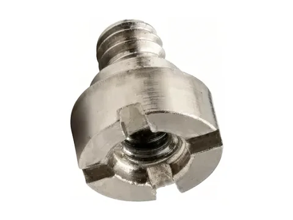
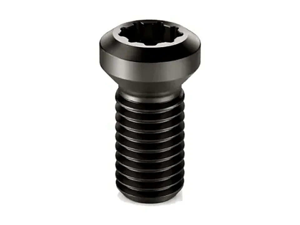
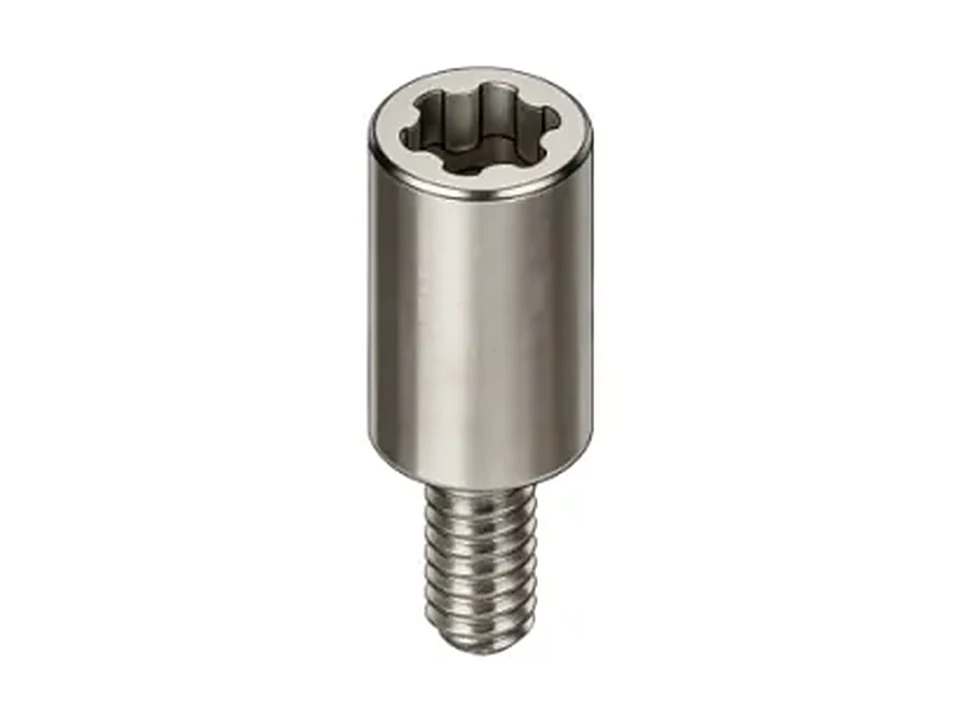
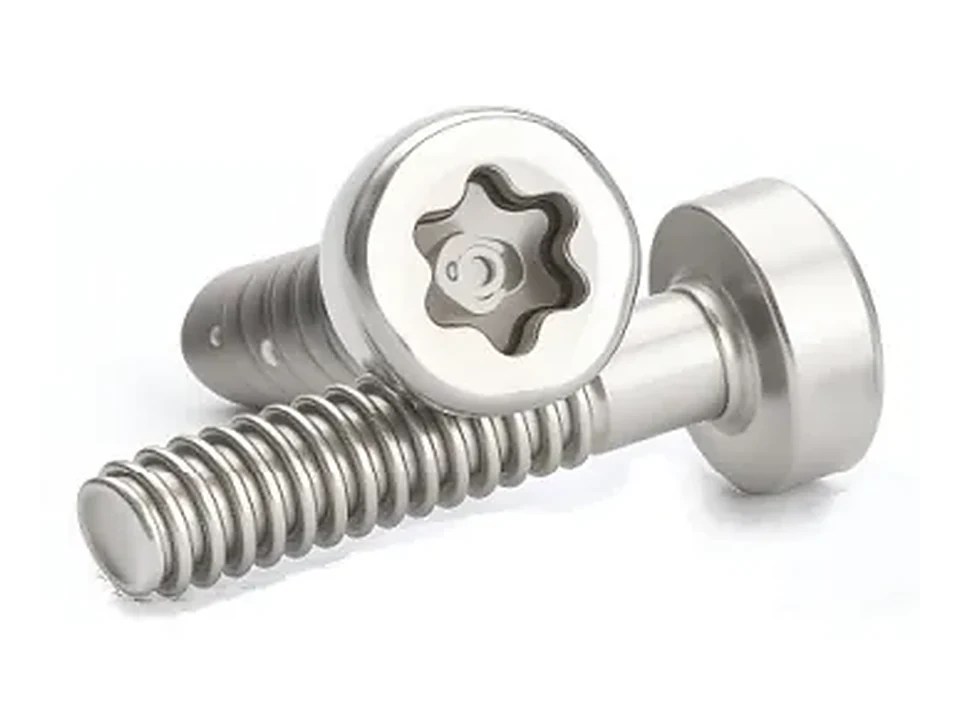
3 SKUsCross-board connections between PCB and modules need either a single part that provides both an internal and an external thread, or tightening within a very small space. Inner-outer super screws are used for board stacking and standoff, and TORX PLUS cylinder heads provide a larger torque-transmitting area on very small heads, which suits high-density assembly.
Four typical micro fastening locations
Phone mid-frames, wearables, AI hardware boards and robot joints — four locations where space, volume and reliability carry different weights.
Phone mid-frames and camera modules
The main battleground for M0.6–M1.2, where clearances are counted in fractions of a millimetre. Mid-frames and brackets usually take ultra-low head parts, while module locations require plating that neither clogs the thread nor sheds particles (shedding contaminates the lens). Such products usually pair with brass inserts or heat-set nuts, and the screw must withstand repeated assembly.
Wearables and watches
Micro connections in movements and watch cases call for corrosion resistance, long-term reliability and controlled weight. Materials tend towards stainless (low permeability) and titanium; for visible parts, coating colour consistency and wear resistance matter, and PVD processes are a common option here.
AI servers and optical modules
Micro fastening on high-density PCBs, SMT surface-mount nuts and optical module housing connections. The first requirement in these cases is SMT-line compatibility: tape-and-reel packaging, a flat pick-up surface and reflow temperature resistance. Locking and temperature resistance come next, and near liquid-cooling modules condensation must also be considered.
Humanoid robots and precision actuators
Micro high-strength connections of M1–M4 in joints must be maintenance-free and resist high-frequency reciprocation. Here micro parts need low heads to save space, pre-applied adhesive or serrated locking, and lot consistency — a robot carries hundreds to a thousand of them, and any single failure means stripping the machine.
Selection logic for micro fasteners
Count the threads first, then the space, then fix material and drive, and finally confirm whether it can run on the line.
The selection sequence for micro screws is completely different from that for large sizes: you do not start with the strength class, you start with the question of whether there is enough thread engagement. On M0.6 the effective engagement may be barely over 1 mm, and without enough threads any strength class is meaningless. The six sections below draw on the in-house technical articles “Micro Screws M0.6–M1.4: Machining Difficulties, Tolerances and AI Hardware Applications” and “Key Technical Points of Precision Small Screws”, together with the product clauses of six micro and board-level precision parts on this site.
Step 1: Count the threads before discussing strength
The load capacity of a threaded joint comes from the number of engaged threads, not from the overall screw length. With a pitch of about 0.15 mm on M0.6, a 1 mm engagement holds only six or seven threads, and typically only the first 3–5 carry real load. Design therefore starts by calculating the required number of engaged threads from the strength of the base material, then working back to panel thickness or insert depth.
Industry practice is to control 3–5 threads of effective engagement: fewer and the threads shear easily; more and the load distribution becomes uneven, with the trailing threads barely participating. This matters especially on micro parts, because there is often no room for a little extra length.
- Machine thread (M) → used with a nut or an internally threaded hole, suitable for repeated disassembly
- Self-tapping thread (B) → driven directly into plastic or thin metal, not for repeated disassembly
- Hold effective engagement at 3–5 threads; if short, switch to an insert or increase thickness
- A thin wall cannot be thickened → transfer the thread to an inner-outer part or an insert
Step 2: Space decides head style and drive
On micro parts the head height is often the design bottleneck. An ultra-low head saves height but leaves a small bearing area and a low torque ceiling; a large head (such as the extra-short large-head type) spreads the contact pressure but takes up more plan area. The two trade off against each other, so choose by the actual interference situation.
The drive recess governs whether torque can be transmitted at all: a cross recess is universal and bits are easy to obtain, but on very small heads it slips easily; TORX / TORX PLUS has a large bearing area and resists cam-out, which suits high-density automated driving; serrated and CD-textured heads reduce the risk of cam-out by increasing friction at the head.
Step 3: Choose the material by function, not by price
Carbon steel SWRCH10A/18A/22A can be carburized to raise surface hardness and wear resistance and is the standard choice for light-load structural and plastic parts. SUS302HQ/304/316 are low-permeability and corrosion resistant, which suits medical and interference-sensitive locations, but their strength cannot be raised by heat treatment. Where high strength and stainless properties are both required, use hardenable SUS410 or carburized carbon steel; for strict non-magnetic requirements, choose titanium TA2.
The most common misjudgement here is expecting high strength from SUS304. Stainless steel cannot be strengthened by hardening the way carbon steel can; when high-strength micro parts are needed, either change the material or compensate through structure and size — ordinary SUS304 will not become stronger by hardening.
Step 4: Design the coating and the thread tolerance together
On micro parts the coating thickness and the thread tolerance sit in the same order of magnitude: too thick and the gauge fails, too thin and corrosion resistance falls short. The drawing therefore cannot simply say “nickel plated”; it must give pre-plating dimensions and post-plating go/no-go requirements so that the process has room to allow for the coating.
Another implicit requirement is no particle shedding. Near camera modules and optical assemblies, flakes of coating or chips from thread cutting cause rejects directly. For such locations, choose a process with good adhesion and control cleanliness before assembly.
Step 5: Line compatibility is the final veto
Micro screws almost always run on automatic driving or SMT lines, so they must be tape-and-reel packable, have a flat pick-up surface and keep pace with the cycle. Head diameter, length and recess depth must vary only minimally within a lot, otherwise parts jam, the bit slips or the head breaks.
That means three questions at selection: can it be taped? Is the reel compatible with the placement or driving machine? Is lot consistency backed by data? If any one of the three cannot be answered, all the earlier performance discussion is meaningless.
Step 6: What to Put in the Acceptance Criteria
Dimensions and thread: head diameter, shank diameter, length and recess depth inspected 100% or by sampling against the drawing; threads checked with go/no-go gauges (6g/6H), and for micro parts a thread-form projection or vision measurement is recommended in addition. Mechanical properties: tensile and hardness tests to the corresponding class of GB/T 3098.1, with case depth checked separately on carburized parts.
Assembly performance: run a driving test at 70–80% of breaking torque and confirm no head breakage and no thread stripping; for production lots, run tape peel and pick-up tests; for surfaces, run a salt-spray test to GB/T 10125 where the customer requires it, and check that the plating does not clog the thread.
A total-cost optimisation partner from prototype design to after-sales
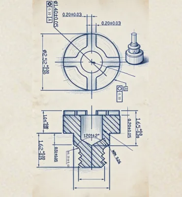
Six professional services cover selection, samples, validation and volume ramp-up, turning "will this screw work" into a verifiable engineering conclusion.

Fast engineering samples
Professional training
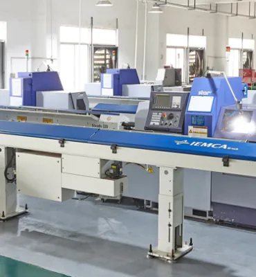
Professional testing services
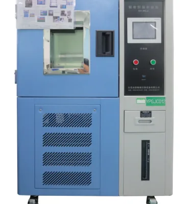
Professional design consulting
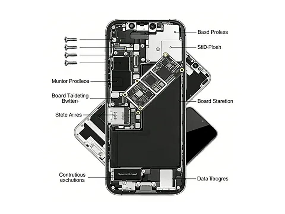
Continuous process optimisation
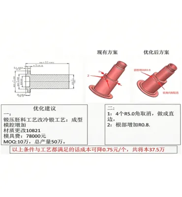
Professional teardown analysis
From thread-count calculation to tape-based launch
Validation of micro parts passes three gates: are there enough threads, is the lot consistent, and can it be taped.
Thread-count and space calculation
Calculate the required engaged threads (3–5) from the base material strength, then check panel thickness, available height and bit clearance.
Head style and drive selection
Choose an ultra-low head or a large head according to interference, and a cross, Torx or serrated drive according to the automated driving requirement.
Fixing material and coating grade
Select carburized carbon steel, SUS, SUS410 or titanium according to strength, low-permeability, non-magnetic and corrosion requirements, then confirm the coating and the tolerance allowance.
Driving and consistency validation
Run a driving test at 70–80% of breaking torque, sample head diameter, length and recess depth for lot-to-lot variation, and confirm no head breakage and no thread stripping.
Tape and line validation
Run tape peel, pick-up and cycle-time validation, and release to production only after compatibility with the placement or automatic driving machine is confirmed.
Frequently asked questions about micro fasteners
How much tensile load can an M0.6 micro screw take?
Why do micro screws keep slipping the bit?
Can small screws reach high strength with SUS304?
Does the coating on micro parts affect the go/no-go gauge?
Why must micro screws be tape-packed?
How is preload set on micro screws?
Continue below
Send panel thickness, thread count and bit clearance, and we will specify parts by thread count
Send the base material and panel thickness, available height, bit clearance, automated driving method and lot size, and we will calculate the engaged thread count and head style and supply tape-compatible samples.