
Humanoid Robot Joint Fastening: Precision Connection Challenges under High Integration
Executive Summary
Inside a humanoid robot joint, space is measured in millimeters, life in millions of cycles, and interference in magnetic flux. The fastener here is no longer just a connector but a functional element that directly determines joint accuracy, life, and reliability. This article breaks down five conflicting constraints brought by high integration and four typical joint connection locations, and gives the selection thinking and verification path for miniature precision fasteners.
Table of Contents
The most expensive thing in a joint is not the motor
Technical discussion of humanoid robots mostly centers on joint modules, dexterous hands, and motion-control algorithms, while fasteners are often dismissed in one line in the structural-parts BOM. But in actual engineering, what is hardest to solve is often the invisible connections inside the joint.
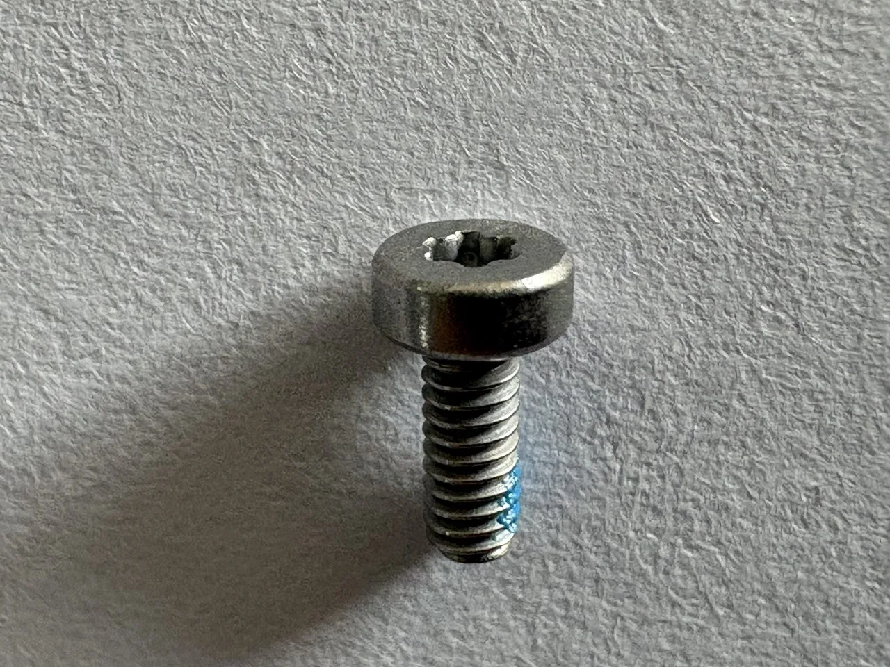
The reason lies in the extreme space constraint. One rotary joint simultaneously packs a frameless torque motor, a harmonic reducer, an encoder, a brake, a driver board, and cable routing, leaving the fastener often only a few millimeters of space, while the load it bears is not small—the joint bears torque, shock, and alternating loads, and may even be the whole machine's load path.
What is more troublesome is that failure consequences are amplified: the preload decay of one screw may manifest as increased joint backlash, reduced positioning accuracy, or abnormal noise, ultimately affecting whole-machine performance. The fastener's status in a joint is closer to a functional element than a connector.
Five constraints on joint fastening
Summarizing the humanoid robot joint's requirements on fasteners yields five mutually conflicting constraints that must be weighed together at the scheme stage.
| Constraint | Specific Requirement | Challenge to the Fastener |
|---|---|---|
| Miniaturization | Mounting space measured in millimeters; commonly M1.6–M3 | The smaller the size, the harder the thread form and drive recess are to control |
| Lightweighting | End effectors and arms are extremely weight-sensitive | Need high-strength light materials, but strength must not drop |
| High vibration resistance | Frequent joint motion; continuous vibration and shock | Anti-loosening requirement higher than traditional industrial equipment |
| Long life | Design life on the order of millions of motions | The joint must maintain stable preload under repeated cycling |
| Non-magnetic, low interference | Close to encoders and drive circuits | Material permeability affects measurement accuracy |
The precision boundary of miniature fasteners
When the size shrinks below M2, the manufacturing-precision meaning of a fastener changes qualitatively. At this point, what affects assembly yield is often not whether it is within tolerance, but whether the within-batch distribution is concentrated.
- Dimensional accuracy: after the tolerance-band width of miniature threads shrinks proportionally, the absolute value is tiny; thread-form error directly affects meshing state and driving torque.
- Drive-recess accuracy: a few micrometers of fluctuation in recess depth or width may cause bit cam-out or thread stripping, which is decisive for automated locking lines.
- Batch consistency: small-size parts are more prone to material mixing and foreign-matter attachment during cleaning, coating, and packaging, so cleanliness requirements are higher than for regular sizes.
| Process | Advantage | Limitation |
|---|---|---|
| Cold heading | Continuous metal flow line, high strength, high efficiency | Die-life pressure at ultra-small sizes |
| CNC turning | High precision; suitable for small batches and non-standard structures | Flow line cut; low efficiency |
| Cold heading + finishing | Balances strength and precision | Added steps; higher cost |
Typical locations of connections inside the joint
Taking a joint apart, fasteners concentrate in four locations, each with different risk points.
| Location | Function | Main Risk | Fastener Concern |
|---|---|---|---|
| Reducer and output flange | Transmit torque | Loosening causes increased backlash and abnormal noise | Anti-loosening, preload stability, fatigue |
| Motor rotor and encoder disk | Position feedback | Micro-motion causes calibration drift | Non-magnetic material, dynamic balance, miniature precision |
| Driver board and structural parts | Fix the PCB | Vibration causes solder-joint and connection fatigue | Low profile, anti-loosening, automation-friendly |
| Housing and joint shell | Protection and load bearing | Corrosion, appearance, assembly tact time | Coating and torque consistency, maintainability |
There is also a special feature of anti-loosening: the joint's vibration signature is low frequency but extremely high cycle count, accompanied by frequent reversing shocks. Under such conditions, traditional friction-type anti-loosening decays faster; a solution with mechanical locking or a pre-applied adhesive layer is more appropriate.
Material and coating selection
Different positions inside the joint have very different material and coating requirements; choosing by the combinations in the table below avoids the most common mismatches.
| Demand Combination | Recommended Material Direction | Surface Treatment Direction |
|---|---|---|
| Lightweight + high strength | High-strength aluminum alloy | Anodizing |
| Corrosion resistance + non-magnetic | Austenitic stainless steel | Passivation or coating |
| High strength + non-magnetic | Titanium alloy | Anodizing or solid lubrication |
| High wear resistance + low friction | Alloy steel | DLC or PVD coating |
| Anti-loosening + fine adjustment | Alloy steel or stainless steel | Pre-applied adhesive microcapsule layer |
Verification path and conclusion
Humanoid robots are still in a rapid iteration phase and lack a mature standards system, so the design of the verification method is more critical than the selection itself. The following sequence is recommended.
- Torque-clamp force test: confirm the friction coefficient and scatter of miniature fasteners at very small sizes; this is the basis of all subsequent calculations.
- Vibration and cyclic loading test: simulate the actual reversing-shock count of the joint, observe the preload-decay curve, and judge whether the anti-loosening solution is sufficient.
- Repeated disassembly test: simulate the number of removals according to the debugging process, and evaluate thread wear and galling risk.
- Non-magnetic and magnetic-interference assessment: replace fasteners of different materials near the sensor and compare calibration differences.
- Failure-part failure analysis: perform fracture and cross-section analysis on joints that fail after testing, reverse-confirming whether it is a selection problem or a process problem.
YF Zhichengjia's vision is to become an innovation leader in the fastener field. Around the emerging direction of embodied AI, with our capabilities in professional design consulting, rapid engineering samples, professional testing, and professional failure analysis, we work with customers to solve those millimeter-level connection problems inside the joints at the prototype stage.