
Wire Thread Insert Introduction
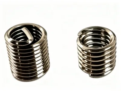
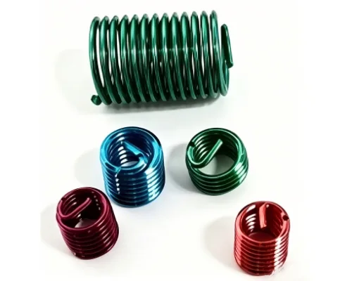
A new type of internal-thread fastener: an embedded thread-reinforcement element made of high-strength stainless steel wire. Its performance exceeds that of a directly tapped internal thread in every respect. It is used to repair or reinforce threaded holes in soft materials (such as aluminum, magnesium and plastics), giving them high strength, wear resistance and anti-loosening properties.
Product Advantages
1. Wire thread inserts are light yet strong, usually made of hardened 304 stainless steel with hardness HRC 43-50 and strength generally not below 1370MPa.
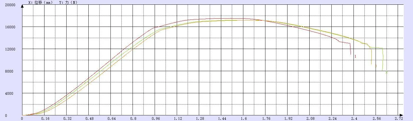
Wire insert material tensile strength test photo
2. Wire thread inserts can raise the internal thread strength of light-alloy materials (magnesium, aluminum, etc.) up to grade 12, and distribute the load on the internal thread more evenly — without an insert, the first thread typically carries 50% of the force.
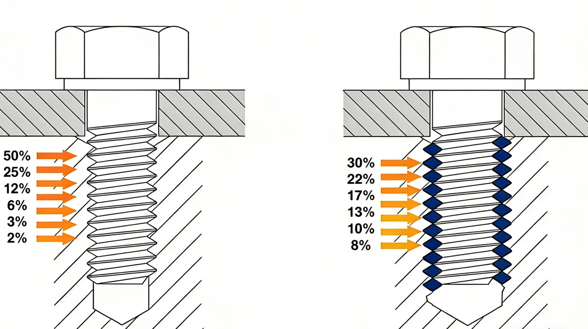
Standard tapped hole Tapped hole with wire thread insert
These two advantages allow light-alloy threaded holes fitted with wire inserts to mate with high-strength bolts of grade 8.8 and above.
How Wire Thread Inserts Work
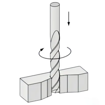
1. Drilling:When using standard taps, pay attention to diameter selection. Avoid counterbores where possible.
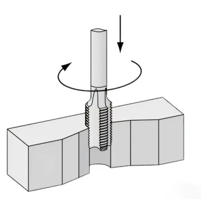
2. Tapping:Use the correct tap to cut the base thread for the selected thread size.
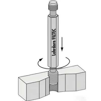
3. Thread Inspection:To check the base thread, use a gauge for inspection.
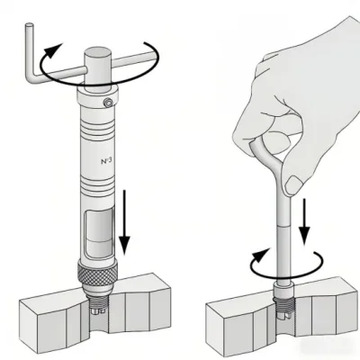
4. Installation:The wire thread insert can be screwed directly into the base thread. The end of the insert should be screwed at least 1/4 turn below the material surface.
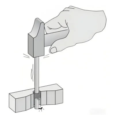
5. Tang Breaking:For through holes, use a tang break-off tool to snap the tang. For inserts in blind holes, the tang may remain in place if maximum insertion depth is considered.
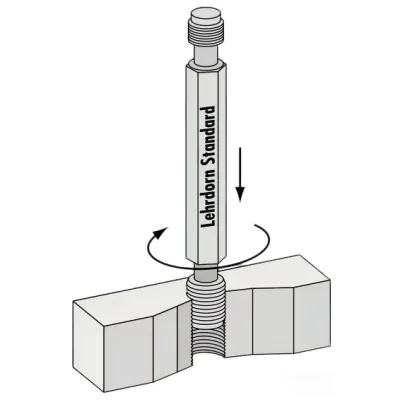
6. Inspection:After removing the tang, inspection can be repeated.
Note: step 5 can be skipped for tangless inserts
Installation Precautions
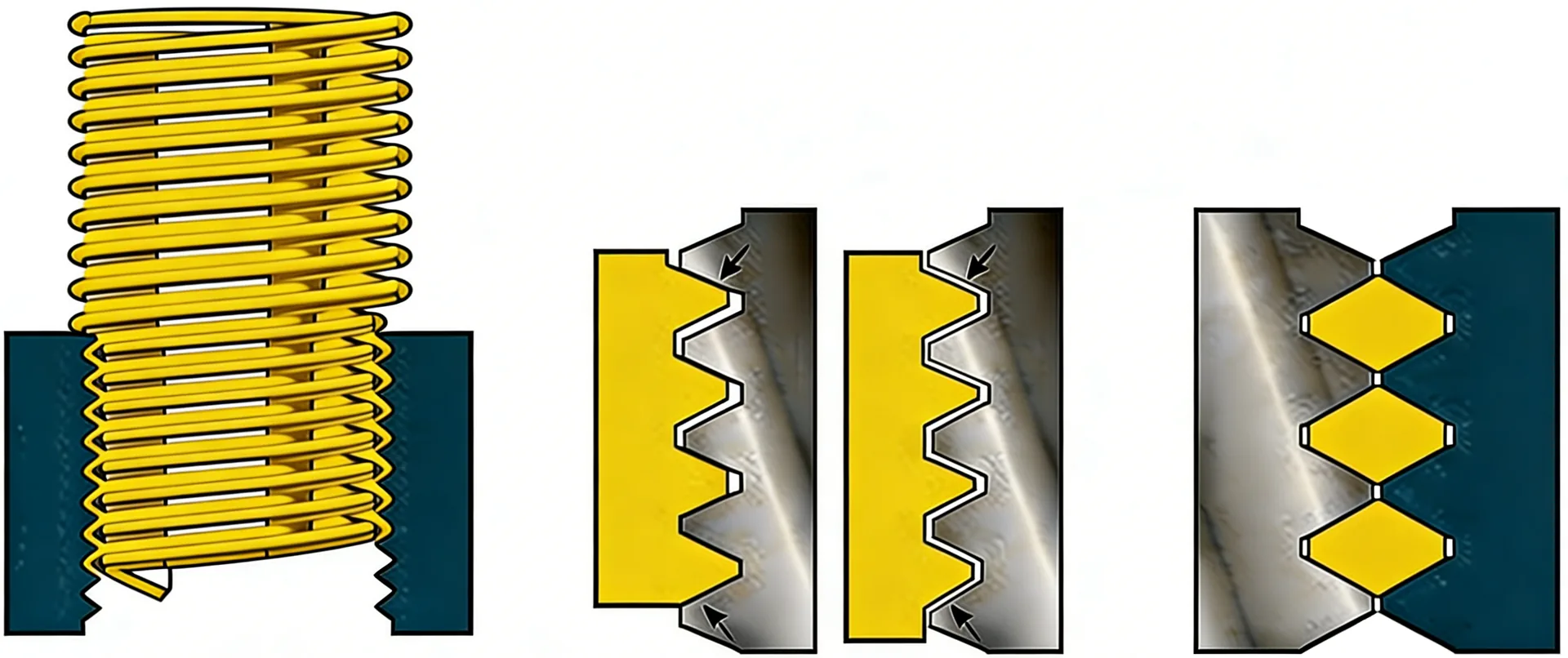
Keys to installation: screw in perpendicular, matched tools, stop steady when in place
1. Position and screw in: mount the insert on the special mandrel, align with the pre-tapped hole and screw in perpendicular until part of the insert enters.
2. Avoid errors: as shown, keep the tool perpendicular to prevent tilting caused by the “angle problem”; use a tap matching the pitch to avoid the “pitch problem” that prevents insertion or causes thread skipping.
3. Install in place: as shown, screw the insert in to the specified depth (usually about one pitch left below the hole mouth); the driving tang remains exposed, ready for subsequent processing.
Tool display
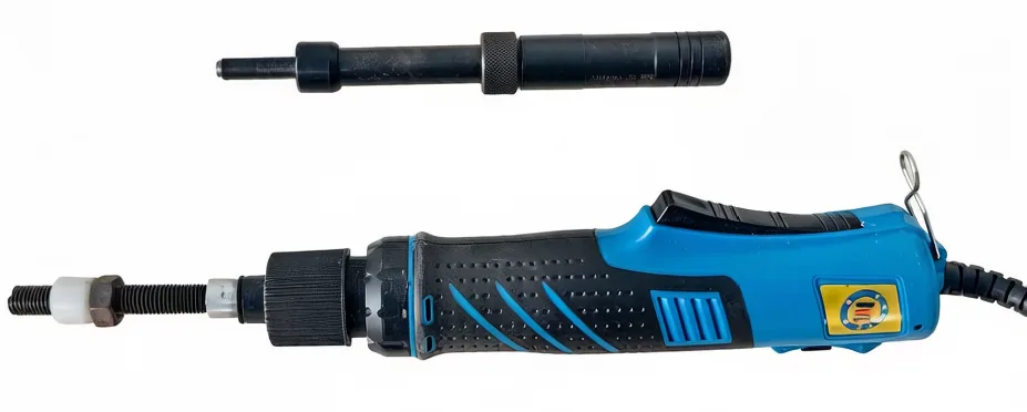
Installation tools
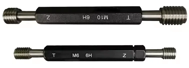
Inspection tools
Product Features
1. Materials include stainless steel SUS304 and SUS316, phosphor bronze, and high-temperature INCONEL nickel alloy.
2. Surface treatments include lubrication, tin plating, zinc plating, silver plating (for high temperature), etc.
3. Sizes from M2 to M39.
4. Threads include coarse and fine pitch.
5. Lengths come in 1D, 1.5D, 2D, 2.5 and 3D — five standard options; custom lengths are available on request.
6. Two types: standard and self-locking.
7. Two styles: with tang and tangless.
8. Appearance colors such as red or green can be applied as required.
Industry Applications
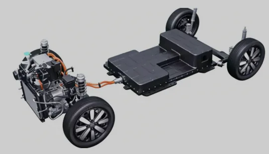
New Energy Vehicles
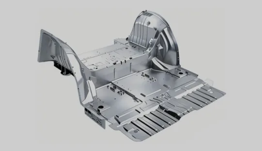
Light-Alloy Industry

Embodied Intelligence

HPC AI Server

Industrial Electronics

Consumer Electronics

Low-altitude Economy

Aerospace Industry
Wire Thread Insert Standards
Table 1 Metric thread tap drill depth details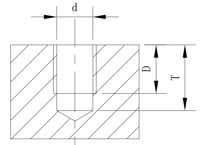
Table 1 Metric thread tap drill depth details
| Metric Coarse Thread | Pitch | Tap Drill d | Drilling Depth T | Thread Depth D | Metric Fine Thread | Pitch | Tap Drill | Drilling Depth | Thread Depth |
|---|---|---|---|---|---|---|---|---|---|
| M2.0 | 0.4 | 1.6 | 6 | 4 | M2.5 | 0.35 | 2.2 | 6 | 4 |
| M2.2 | 0.45 | 1.75 | 6 | 4 | M3.5 | 0.35 | 2.7 | 8 | 6 |
| M2.3 | 0.45 | 1.9 | 6 | 4 | M4.0 | 0.5 | 3.5 | 9 | 7 |
| M2.5 | 0.45 | 2.1 | 7 | 4.5 | M4.5 | 0.5 | 4 | 9 | 7 |
| M2.6 | 0.45 | 2.2 | 7 | 4.5 | M5.0 | 0.5 | 4.5 | 14 | 11 |
| M3.0 | 0.5 | 2.5 | 8 | 6 | M5.5 | 0.5 | 5 | 14 | 11 |
| M3.5 | 0.6 | 2.9 | 8 | 6 | M6.0 | 0.75 | 5.3 | 15 | 12 |
| M4.0 | 0.7 | 3.3 | 9 | 7 | M7.0 | 0.75 | 6.3 | 15 | 12 |
| M4.5 | 0.75 | 3.25 | 9 | 7 | M8.0 | 1 | 7 | 18 | 15 |
| M4.5 | 0.75 | 3.8 | 10 | 8 | M8.0 | 0.75 | 7.3 | 18 | 15 |
| M5.0 | 0.8 | 4.2 | 14 | 11 | M8.5 | 0.75 | 7.3 | 18 | 15 |
| M5.0 | 0.9 | 4.1 | 14 | 11 | M9.0 | 0.75 | 8 | 18 | 15 |
| M6.0 | 1 | 5 | 15 | 12 | M9.0 | 0.75 | 8.3 | 18 | 15 |
| M7.0 | 1 | 6 | 15 | 12 | M10.0 | 1.25 | 8.8 | 20 | 17 |
| M8.0 | 1.25 | 6.8 | 18 | 15 | M10.0 | 0.75 | 9 | 20 | 17 |
| M9.0 | 1.25 | 7.8 | 18 | 15 | M11.0 | 0.75 | 9.3 | 20 | 17 |
| M10.0 | 1.5 | 8.5 | 20 | 17 | M11.0 | 1.25 | 10.3 | 20 | 17 |
| M11.0 | 1.5 | 9.5 | 20 | 17 | M12.0 | 1.25 | 10.8 | 20 | 17 |
| M12.0 | 1.75 | 10.3 | 20 | 17 | M12.0 | 1.25 | 10.8 | 20 | 17 |
| M14.0 | 2 | 12 | 25 | 22 | M12.0 | 1.25 | 10.8 | 20 | 17 |
| M16.0 | 2 | 14 | 25 | 22 | M14.0 | 1.5 | 12.5 | 25 | 22 |
| M18.0 | 2.5 | 15.5 | 25 | 22 | M15.0 | 1.5 | 13.5 | 25 | 22 |
| M20.0 | 2.5 | 17.5 | 25 | 22 | M16.0 | 1.5 | 14.5 | 25 | 22 |
| M22.0 | 2.5 | 19.5 | 25 | 22 | M20.0 | 1.5 | 15 | 25 | 22 |
| M24.0 | 3 | 21 | 25 | 22 | M22.0 | 2 | 18 | 25 | 22 |
| M27.0 | 3 | 24 | 25 | 22 | M24.0 | 2 | 18 | 25 | 22 |
| M30.0 | 3.5 | 26.5 | 25 | 22 | M27.0 | 2 | 16.5 | 25 | 22 |
| M33.0 | 3.5 | 29.5 | 25 | 22 | M30.0 | 2 | 16.5 | 25 | 22 |
| M36.0 | 4 | 32 | 25 | 22 | M33.0 | 2 | 16.5 | 25 | 22 |
| M39.0 | 4 | 35 | 25 | 22 | M36.0 | 2 | 16.5 | 25 | 22 |
Wire Thread Insert Standards
Table 2 GB/T 24425.1-2009 wire thread insert parameters — (coarse thread)
Table 2 GB/T 24425.1-2009 wire thread insert parameters — (coarse thread)
| Wire Thread Insert Specification | Guide Size dy | Free State Diameter Dz | Nominal Length n*p | Free State Coils N (min) | Installed Length | ||||
|---|---|---|---|---|---|---|---|---|---|
| min | max | min | max | min | max | min | max | ||
| M2 | 2.53 | 2.7 | 1d | 3 | 3.4 | 1.6 | 1.8 | ||
| 1.5d | 5.3 | 5.6 | 2.6 | 2.8 | |||||
| 2d | 7.6 | 7.9 | 3.6 | 3.8 | |||||
| 2.5d | 9.9 | 10.2 | 4.6 | 4.8 | |||||
| 3d | 12.2 | 12.4 | 5.5 | 5.8 | |||||
| M2.5 | 3.2 | 3.7 | 1d | 3.3 | 3.8 | 2.05 | 2.375 | ||
| 1.5d | 5.9 | 6.3 | 3.3 | 3.525 | |||||
| 2d | 8.5 | 8.8 | 4.55 | 4.775 | |||||
| 2.5d | 11.1 | 11.4 | 5.8 | 6.025 | |||||
| 3d | 13.6 | 13.9 | 7.05 | 7.275 | |||||
| M3 | 3.8 | 4.35 | 1d | 3.6 | 4.3 | 2.5 | 2.75 | ||
| 1.5d | 6.3 | 7.1 | 4 | 4.25 | |||||
| 2d | 9 | 9.8 | 5.5 | 5.75 | |||||
| 2.5d | 11.8 | 12.6 | 7 | 7.25 | |||||
| 3d | 14.5 | 15.3 | 8.5 | 8.75 | |||||
| M4 | 5.05 | 5.6 | 1d | 3.6 | 4.2 | 3.3 | 3.65 | ||
| 1.5d | 6.3 | 6.9 | 5.3 | 5.65 | |||||
| 2d | 9.1 | 9.5 | 7.3 | 7.65 | |||||
| 2.5d | 11.8 | 12.2 | 9.3 | 9.65 | |||||
| 3d | 14.4 | 14.9 | 11.3 | 11.65 | |||||
| M5 | 6.25 | 6.8 | 1d | 4 | 4.7 | 4.2 | 4.6 | ||
| 1.5d | 6.8 | 7.6 | 6.7 | 7.1 | |||||
| 2d | 9.6 | 10.6 | 9.2 | 9.6 | |||||
| 2.5d | 12.4 | 13.5 | 11.7 | 12.1 | |||||
| M6 | 7.28 | 7.58 | 7.58 | 7.95 | 1d | 3.8 | 4.5 | 5 | 5.5 |
| 1.5d | 6.5 | 7.3 | 8 | 8.5 | |||||
| 2d | 9.2 | 10.2 | 11 | 11.5 | |||||
| 2.5d | 12 | 13 | 14 | 14.5 | |||||
| 3d | 14.6 | 15.8 | 17 | 17.5 | |||||
| M7 | 8.28 | 8.58 | 8.58 | 9.2 | 1d | 4.7 | 5.4 | 6 | 6.5 |
| 1.5d | 7.9 | 8.8 | 9.5 | 10 | |||||
| 2d | 11 | 12.1 | 13 | 13.5 | |||||
| 2.5d | 14.2 | 15.4 | 16.5 | 17 | |||||
| 3d | 17.3 | 18.7 | 20 | 20.5 | |||||
| M8 | 9.55 | 9.85 | 9.85 | 10.35 | 1d | 4.4 | 4.9 | 6.75 | 7.375 |
| 1.5d | 7.3 | 8 | 10.75 | 11.375 | |||||
| 2d | 10.3 | 11.1 | 14.75 | 15.375 | |||||
| 2.5d | 13.3 | 14.1 | 18.75 | 19.375 | |||||
| 3d | 16.4 | 17.2 | 22.75 | 23.375 | |||||
| M10 | 11.82 | 12.1 | 12.1 | 12.8 | 1d | 4.7 | 5.2 | 8.5 | 9.25 |
| 2d | 11 | 11.6 | 18.5 | 19.25 | |||||
| 2.5d | 14.2 | 14.8 | 23.5 | 24.25 | |||||
| 3d | 17.3 | 18 | 28.5 | 29.25 | |||||
| M12 | 14.2 | 14.5 | 14.5 | 15 | 1d | 4.8 | 5.4 | 10.25 | 11.125 |
| 1.5d | 8.1 | 8.7 | 16.25 | 17.125 | |||||
| 2d | 11.3 | 12 | 22.25 | 23.125 | |||||
| 2.5d | 14.6 | 15.3 | 28.25 | 29.125 | |||||
| 3d | 17.8 | 18.6 | 34.25 | 35.125 | |||||
| M14 | 16.47 | 16.87 | 16.87 | 17.87 | 1d | 4.9 | 5.5 | 12 | 13 |
| 1.5d | 8.3 | 8.9 | 19 | 20 | |||||
| 2d | 11.6 | 12.3 | 26 | 27 | |||||
| 2.5d | 14.9 | 15.6 | 33 | 34 | |||||
| 3d | 18.2 | 19 | 40 | 41 | |||||
| M16 | 18.67 | 18.87 | 18.87 | 19.9 | 1d | 6 | 6.5 | 14 | 15 |
| 1.5d | 9.8 | 10.3 | 22 | 23 | |||||
| 2d | 13.6 | 14.2 | 30 | 31 | |||||
| 2.5d | 17.4 | 18 | 38 | 39 | |||||
| M18 | 21 | 21.4 | 21.4 | 22 | 1d | 5.2 | 6.1 | 15.5 | 16.75 |
| 1.5d | 8.6 | 9.5 | 24.5 | 25.75 | |||||
| 2d | 12.1 | 13 | 33.5 | 34.75 | |||||
| 2.5d | 15.5 | 16.5 | 42.5 | 43.75 | |||||
| 3d | 18.9 | 20 | 51.5 | 52.75 | |||||
| M20 | 23.01 | 23.46 | 23.46 | 24.4 | 1d | 6 | 6.8 | 17.5 | 18.75 |
| 1.5d | 9.7 | 10.7 | 27.5 | 28.75 | |||||
| 2d | 13.5 | 14.6 | 37.5 | 38.75 | |||||
| 2.5d | 17.3 | 18.4 | 47.5 | 48.75 | |||||
| 3d | 21.2 | 22.3 | 57.5 | 58.75 | |||||
| M22 | 25.01 | 25.61 | 25.61 | 26.9 | 1d | 6.7 | 7.6 | 19.5 | 20.75 |
| 1.5d | 10.9 | 11.9 | 30.5 | 31.75 | |||||
| 2d | 15.1 | 16.1 | 41.5 | 42.75 | |||||
| 2.5d | 19.3 | 20.4 | 52.5 | 53.75 | |||||
| 3d | 23.5 | 24.6 | 64.75 | ||||||
| M24 | 27.55 | 28.15 | 28.15 | 29.1 | 1d | 6 | 6.7 | 21 | 22.5 |
| 2.5d | 17.4 | 18.3 | 57 | 58.5 | |||||
| 3d | 21.3 | 22.2 | 69 | 70.5 | |||||
| M27 | 30.55 | 31.15 | 31.15 | 32.4 | 1d | 6.9 | 7.7 | 24 | 25.5 |
| 1.5d | 11.1 | 12.2 | 37.5 | 39 | |||||
| 2d | 15.5 | 16.7 | 52.5 | ||||||
| 2.5d | 19.3 | 20.4 | 64.5 | 66 | |||||
| 3d | 23.9 | 24.7 | 78 | 79.5 | |||||
| M30 | 34.1 | 34.7 | 34.7 | 35.81 | 1d | 6.5 | 7.1 | 26.5 | 28.25 |
| 1.5d | 10.6 | 11.3 | 41.5 | 43.25 | |||||
| 2d | 14.4 | 15.4 | 56.5 | 58.25 | |||||
| 2.5d | 18.7 | 19.2 | 71.5 | 73.25 | |||||
| 3d | 22.8 | 23.4 | 86.5 | 88.25 | |||||
| M33 | 37.09 | 37.7 | 37.7 | 39.01 | 1d | 7.3 | 8.2 | 29.5 | 31.25 |
| 1.5d | 11.8 | 12.9 | 46 | 47.75 | |||||
| 2d | 16.3 | 17.6 | 62.5 | 64.25 | |||||
| 2.5d | 20.8 | 21.3 | 79 | 80.75 | |||||
| M36 | 40.63 | 41.33 | 41.33 | 42.67 | 1d | 6.9 | 7.5 | 32 | 34 |
| 1.5d | 11.2 | 11.9 | 50 | 52 | |||||
| 2d | 15.5 | 16.3 | 68 | 70 | |||||
| 2.5d | 19.7 | 20.3 | 86 | 88 | |||||
| 3d | 24 | 24.6 | 104 | 106 | |||||
| M39 | 43.63 | 44.33 | 44.33 | 45.75 | 1d | 7.7 | 8.3 | 35 | 37 |
| 1.5d | 12.3 | 13 | 54.5 | 56.5 | |||||
| 2d | 17 | 17.7 | 74 | 76 | |||||
| 2.5d | 21.6 | 22.1 | 93.5 | 95.5 | |||||
| 3d | 26.2 | 26.8 | 113 | 115 | |||||
Custom Wire Thread Inserts
Table 3 Custom wire thread insert parameters — (coarse thread)
Table 3 Custom wire thread insert parameters — (coarse thread)
| Wire Thread Insert Specification | Nominal Length n*p | Coils N | Free State Diameter Dz | Color | With Tang / Tang-Free |
|---|---|---|---|---|---|
| M4 | 1d | 3.6-4.2 | 5.05-5.6 | Green | With Tang |
| 3d | 14.4-14.9 | 5.05-5.6 | Natural | With Tang | |
| M5 | 1.5d | 6.8-7.6 | 6.25-6.80 | Red | Blind Hole, 65% Grooving |
| 1.5d | 6.75-7.25 | 6.28-6.8 | Green | With Tang | |
| 1.5d | 6.8-7.6 | 6.15-6.54 | Green | With Tang | |
| 1.5d | / | / | Natural | Tang-Free | |
| 2d | 9.45-9.7 | 6.35-6.6 | Green | With Tang | |
| 2d | 9.6-10.6 | 6.35-6.4 | Natural | With Tang | |
| 2d | / | / | Natural | Tang-Free | |
| M6 | 1.5d | 6.5-7.3 | 7.5-7.55 | Natural | With Tang |
| 2d | 9.2-10.2 | 7.5-7.55 | Natural | With Tang | |
| M7 | 1d | / | / | Natural | With Tang |
| 1.5d | / | / | Red | With Tang | |
| M8 | 1d | 4.55-4.9 | 9.7-9.8 | Natural | Tang-Free |
| 1.5d | 7.3-8.0 | 9.85-10.35 | Natural | With Tang | |
| 2d | 10.3-11.1 | 9.85-10.35 | Natural | With Tang | |
| 2.5d | 13.3-14.1 | 9.85-10.35 | Green | With Tang | |
| M10 | 1.5d | 7.8-8.4 | 12.1-12.8 | Green | With Tang |
| 2d | 11-11.6 | 12.1-12.8 | Green | With Tang | |
| 3d | 20.2-21.6 | 11.87-12.65 | Green | With Tang |
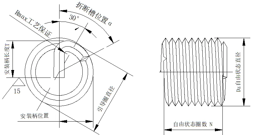
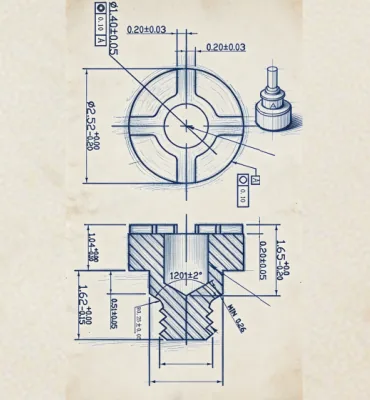
Note: for Tables 2 and 3 see this figure
Wire Thread Insert Standards
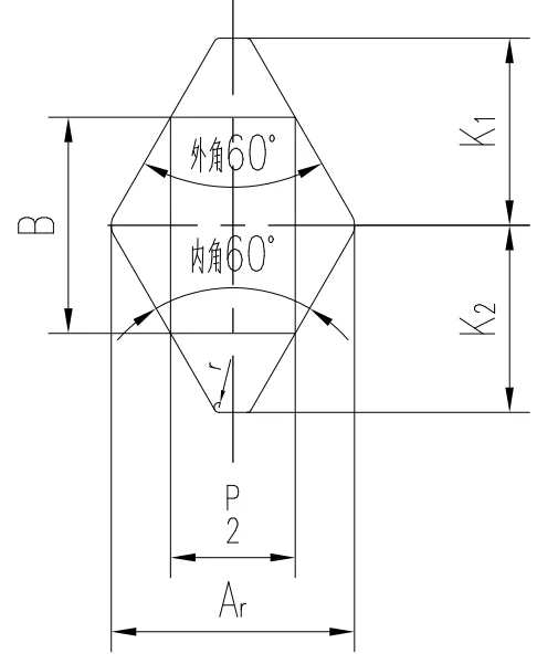
Table 4 GJB 119.4A-2001 wire thread insert parameters
Table 4 GJB 119.4A-2001 wire thread insert parameters
| Pitch P (mm) | Basic Dimension B(mm) | Upper Deviation B (μm) | Lower Deviation B (μm) | Basic Dimension K1(mm) | Upper Deviation K1 (μm) | Lower Deviation K (μm) | Basic Dimension K2(mm) | Upper Deviation K2 (μm) | Lower Deviation K2 (μm) | A min (mm) |
|---|---|---|---|---|---|---|---|---|---|---|
| 0.4 | 0.26 | 0 | -10 | 0.26 | 0 | -50 | 0.217 | 0 | -20 | 0.32 |
| 0.45 | 0.292 | -10 | 0.292 | 0 | -50 | 0.244 | 0 | -20 | 0.36 | |
| 0.5 | 0.325 | 0 | -10 | 0.325 | 0 | -60 | 0.271 | 0 | -25 | 0.4 |
| 0.7 | 0.455 | 0 | -10 | 0.455 | 0 | -60 | 0.379 | 0 | -25 | 0.56 |
| 0.8 | 0.52 | 0 | -12 | 0.52 | 0 | -60 | 0.433 | 0 | -40 | 0.64 |
| 1 | 0.65 | 0 | -12 | 0.65 | 0 | -90 | 0.541 | 0 | -40 | 0.8 |
| 1.25 | 0.812 | 0 | -12 | 0.812 | 0 | -90 | 0.677 | 0 | -55 | 1 |
| 1.5 | 0.974 | 0 | -13 | 0.974 | 0 | -120 | 0.812 | 0 | -55 | 1.2 |
| 1.75 | 1.137 | 0 | 1.137 | 0 | -120 | 0.947 | 0 | -70 | 1.4 | |
| 2 | 1.299 | 0 | -13 | 1.299 | 0 | -120 | 1.083 | 0 | -70 | 1.6 |
| 2.5 | 1.624 | 0 | -13 | 1.624 | 0 | -160 | 1.353 | 0 | -100 | 2 |
| 3 | 1.949 | 0 | -13 | 1.949 | 0 | -160 | 1.624 | 0 | -100 | 2.4 |
| 3.5 | 2.273 | 0 | -13 | 0 | -200 | 1.894 | 0 | -120 | ||
| 4 | 2.598 | 0 | -13 | 2.598 | 0 | -200 | 2.165 | 0 | 3.2 |
Industry Challenges & Solutions
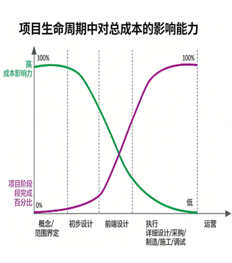
Project Cycle Cost Impact Model
In today's fast-moving environment, the core challenge of product development is that the early decision window is extremely short yet locks in most of the cost, while later correction, despite huge investment, carries extremely high cost — a serious mismatch between risk and return. Companies must therefore make precise judgments at the earliest stage to cope with market uncertainty.
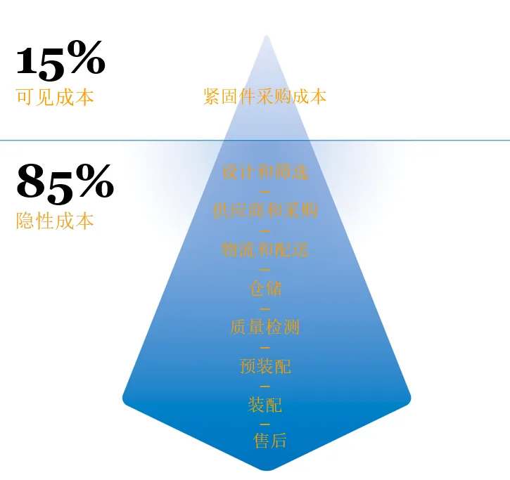
15-85 Rule
Over-focusing on visible purchase cost while ignoring hidden costs that account for 85% leads to fragmented design, supply-chain and after-sales decisions, sharply inflating total life-cycle cost.
YF Zhichengjia's Six Professional Services



Summary
As a high-performance internal-thread reinforcement element, wire thread inserts are widely used in industries with demanding requirements on thread strength, wear resistance and reliability. Through standardized installation processes and a wide range of specification options, they perfectly resolve industry pain points such as insufficient thread strength in soft materials, easy damage and loosening, effectively improving overall equipment stability and service life — the preferred fastening solution for modern industry.